STM32CubeMX第三篇之串口实验
 配置串口的中断
  配置串口的GPIO
  配置完成后,点击确定。
 在本例程中,除了上述分析的自己添加的文档三个文档,STM32CUBE自动生成的代码有:
  二、修改串口初始化
发布日期:2021-05-14 11:31:27
浏览次数:23
分类:精选文章
本文共 7643 字,大约阅读时间需要 25 分钟。
文章目录
前言
本文主要介绍 串口实验 的通过STM32CUBE形式和直接编程模式的不同。
本文可以参考博客<>。两种方式实验的效果完全相同:
- 在程序启动时,会发送信息 hello,zhy!
- 在程序运行时,LED等闪烁。
- 向串口1 发送数据,其会返回相同的数据。
该实验源代码下载
本文主要参考资料:
- 正点原子.STM32F429开发指南-HAL库版本_V1.1
STM32CUBE配置
关于LED灯的配置部分,可以参考博客<>。本文不再重复介绍。
配置串口
- 配置Pinout。本实验使用的是PA9和PA10。首先配置为串口功能,如下图所示:

- 配置configuration。在此处经常需要配置GPIO,NVIC,RCC,USART等。本例程主要演示USART,如下所示:

配置串口的中断 配置串口的GPIO 配置完成后,点击确定。 - 配置中断。

最后,可以按照之前博客<>中介绍的方法生成代码。此处不再介绍。
代码分析与修改
1. 添加代码
添加三部分代码:
- 对列相关
- 延时相关
- 系统相关
其中,前两个部分与博客<>中介绍的完全相同。因为系统初始化还有串口部分都可以自动生成,所以,对系统相关的文件需要修改如下:
头文件与上述博客内容也是一致,如上所示:
/** ****************************************************************************** * @file sys.h * @author zhy * @version 1.0 * @date 2021-01-22 * @brief 系统初始化相关的头文件 ****************************************************************************** */#ifndef _SYS_H#define _SYS_H#include/* 位带操作 */typedef struct{ unsigned int bit0 : 1; unsigned int bit1 : 1; unsigned int bit2 : 1; unsigned int bit3 : 1; unsigned int bit4 : 1; unsigned int bit5 : 1; unsigned int bit6 : 1; unsigned int bit7 : 1; unsigned int bit8 : 1; unsigned int bit9 : 1; unsigned int bit10 : 1; unsigned int bit11 : 1; unsigned int bit12 : 1; unsigned int bit13 : 1; unsigned int bit14 : 1; unsigned int bit15 : 1; unsigned int rsv : 16;} BitBand __attribute__((bitband));extern BitBand PAin;extern BitBand PBin;extern BitBand PCin;extern BitBand PDin;extern BitBand PEin;extern BitBand PFin;extern BitBand PGin;extern BitBand PHin;extern BitBand PIin;extern BitBand PAout;extern BitBand PBout;extern BitBand PCout;extern BitBand PDout;extern BitBand PEout;extern BitBand PFout;extern BitBand PGout;extern BitBand PHout;extern BitBand PIout;#endif
C文件
/** ****************************************************************************** * @file sys.c * @author zhy * @version 1.0 * @date 2021-01-22 * @brief 系统初始化相关,配置RCC时钟,中断分组 ****************************************************************************** */#include "sys.h"#include "stm32f4xx.h"/* 全局变量 */BitBand PAin __attribute__((at(GPIOA_BASE + 16)));BitBand PBin __attribute__((at(GPIOB_BASE + 16)));BitBand PCin __attribute__((at(GPIOC_BASE + 16)));BitBand PDin __attribute__((at(GPIOD_BASE + 16)));BitBand PEin __attribute__((at(GPIOE_BASE + 16)));BitBand PFin __attribute__((at(GPIOF_BASE + 16)));BitBand PGin __attribute__((at(GPIOG_BASE + 16)));BitBand PHin __attribute__((at(GPIOH_BASE + 16)));BitBand PIin __attribute__((at(GPIOI_BASE + 16)));BitBand PAout __attribute__((at(GPIOA_BASE + 20)));BitBand PBout __attribute__((at(GPIOB_BASE + 20)));BitBand PCout __attribute__((at(GPIOC_BASE + 20)));BitBand PDout __attribute__((at(GPIOD_BASE + 20)));BitBand PEout __attribute__((at(GPIOE_BASE + 20)));BitBand PFout __attribute__((at(GPIOF_BASE + 20)));BitBand PGout __attribute__((at(GPIOG_BASE + 20)));BitBand PHout __attribute__((at(GPIOH_BASE + 20)));BitBand PIout __attribute__((at(GPIOI_BASE + 20)));/** * @brief 重构函数 * @note 在printf中自动调用 * @param {int} ch 发送的数据 * @param {FILE} *f 此处用不到 * @retval 当前发送值 */int fputc(int ch, FILE *f){ while ((USART1->SR & USART_SR_TXE) == 0) ; //判断是否发送完成 USART1->DR = (uint8_t)ch; //发送数据 return ch;} 去掉了系统初始化相关内容,将printf相关内容加入其中,这样,附加的内容就添加完毕。
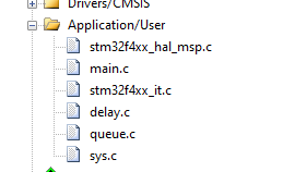
我们所有的配置生成的代码和需要修改的代码都在该文件夹中,如下图所示:
在本例程中,除了上述分析的自己添加的文档三个文档,STM32CUBE自动生成的代码有: - stm32f4xx_hal_msp.c——底层初始化相关
- main.c——主程序
- stm32f4xx_it.c——中断响应相关
2.底层初始化
/* USER CODE BEGIN 0 *//* USER CODE END 0 *//** * Initializes the Global MSP. */void HAL_MspInit(void){ /* USER CODE BEGIN MspInit 0 */ /* USER CODE END MspInit 0 */ HAL_NVIC_SetPriorityGrouping(NVIC_PRIORITYGROUP_2); /* System interrupt init*/ /* MemoryManagement_IRQn interrupt configuration */ HAL_NVIC_SetPriority(MemoryManagement_IRQn, 0, 0); /* BusFault_IRQn interrupt configuration */ HAL_NVIC_SetPriority(BusFault_IRQn, 0, 0); /* UsageFault_IRQn interrupt configuration */ HAL_NVIC_SetPriority(UsageFault_IRQn, 0, 0); /* DebugMonitor_IRQn interrupt configuration */ HAL_NVIC_SetPriority(DebugMonitor_IRQn, 0, 0); /* SysTick_IRQn interrupt configuration */ HAL_NVIC_SetPriority(SysTick_IRQn, 0, 0); /* USER CODE BEGIN MspInit 1 */ /* USER CODE END MspInit 1 */} 该函数被函数UAL_Init()函数最后调用。通过该函数设置了中断优先组为2。
void HAL_UART_MspInit(UART_HandleTypeDef* huart){ GPIO_InitTypeDef GPIO_InitStruct; if(huart->Instance==USART1) { /* USER CODE BEGIN USART1_MspInit 0 */ /* USER CODE END USART1_MspInit 0 */ /* Peripheral clock enable */ __HAL_RCC_USART1_CLK_ENABLE(); /**USART1 GPIO Configuration PA9 ------> USART1_TX PA10 ------> USART1_RX */ GPIO_InitStruct.Pin = GPIO_PIN_9|GPIO_PIN_10; GPIO_InitStruct.Mode = GPIO_MODE_AF_PP; GPIO_InitStruct.Pull = GPIO_PULLUP; GPIO_InitStruct.Speed = GPIO_SPEED_FREQ_VERY_HIGH; GPIO_InitStruct.Alternate = GPIO_AF7_USART1; HAL_GPIO_Init(GPIOA, &GPIO_InitStruct); /* Peripheral interrupt init */ HAL_NVIC_SetPriority(USART1_IRQn, 3, 3); HAL_NVIC_EnableIRQ(USART1_IRQn); /* USER CODE BEGIN USART1_MspInit 1 */ /* USER CODE END USART1_MspInit 1 */ }} 该函数被HAL_UART_MspInit()函数调用。主要设置了串口相关的GPIO设置方法,以及串口对应的中断。
3.中断服务函数
/*** @brief This function handles USART1 global interrupt.*/void USART1_IRQHandler(void){ /* USER CODE BEGIN USART1_IRQn 0 */ /* USER CODE END USART1_IRQn 0 */ HAL_UART_IRQHandler(&huart1); /* USER CODE BEGIN USART1_IRQn 1 */ /* USER CODE END USART1_IRQn 1 */} 与本实验有关的串口中断服务函数原有定义为上文。但是,为了执行效率,不需要这么复杂。结合博客<>中的案例,将该函数修改为:
/*** @brief This function handles USART1 global interrupt.*/void USART1_IRQHandler(void){ /* USER CODE BEGIN USART1_IRQn 0 */ /* USER CODE END USART1_IRQn 0 */ if ((USART1->SR & USART_SR_RXNE) && (USART1->CR1 & USART_CR1_RXNEIE)) //当接收中断置位且有中断标记 { InQueue(&queueRx, USART1->DR); //将接收的内容放入队列,读取寄存器,自动清除中断标记位 } /* USER CODE BEGIN USART1_IRQn 1 */ /* USER CODE END USART1_IRQn 1 */} 为了程序可以顺利执行还需要在该文档头部增加内容:

至此,中断服务部分修改完毕。
4. 主文档
一、添加头文件:
#include "stm32f4xx_hal.h"#include "queue.h"#include "sys.h"#include "delay.h"
添加外部全局变量引用:
extern Queue QueueRx;
总体如下:
二、修改串口初始化 void MX_USART1_UART_Init(void){ UART_HandleTypeDef huart1; //将全局变量添加到此 huart1.Instance = USART1; huart1.Init.BaudRate = 115200; huart1.Init.WordLength = UART_WORDLENGTH_8B; huart1.Init.StopBits = UART_STOPBITS_1; huart1.Init.Parity = UART_PARITY_NONE; huart1.Init.Mode = UART_MODE_TX_RX; huart1.Init.HwFlowCtl = UART_HWCONTROL_NONE; huart1.Init.OverSampling = UART_OVERSAMPLING_16; HAL_UART_Init(&huart1); __HAL_UART_ENABLE_IT(&huart1, UART_IT_RXNE); //开启接收中断} 最后一行为我添加的使能接收中断。
至此程序完成。
int main(void){ /* USER CODE BEGIN 1 */ /* USER CODE END 1 */ /* MCU Configuration----------------------------------------------------------*/ /* Reset of all peripherals, Initializes the Flash interface and the Systick. */ HAL_Init(); /* Configure the system clock */ SystemClock_Config(); /* Initialize all configured peripherals */ MX_GPIO_Init(); MX_USART1_UART_Init(); /* USER CODE BEGIN 2 */ InitQueue(&queueRx); printf("hello, world!\n"); /* USER CODE END 2 */ /* Infinite loop */ /* USER CODE BEGIN WHILE */ while (1) { uint8_t temp = 0; /* USER CODE END WHILE */ while (DeQueue(&queueRx, &temp)) { while ((USART1->SR & USART_SR_TXE) == 0) ; USART1->DR = temp; } PBout.bit0=0; PBout.bit1=1; delay_ms(20); PBout.bit0=1; PBout.bit1=0; delay_ms(20); /* USER CODE BEGIN 3 */ } /* USER CODE END 3 */} 主程序和原来大致一致。
实验结果

发表评论
最新留言
哈哈,博客排版真的漂亮呢~
[***.90.31.176]2025年04月08日 21时13分26秒
关于作者

喝酒易醉,品茶养心,人生如梦,品茶悟道,何以解忧?唯有杜康!
-- 愿君每日到此一游!
推荐文章
IAR调试卡顿的解决办法
2021-05-13
Course Schedule II
2021-05-13
Django ORM操作
2021-05-13
京喜小程序体验评分优化实践
2021-05-13
C#中文转换成拼音
2021-05-13
C++错误笔记
2021-05-13
【无线通信模块】GPRS DTU不稳定和容易掉线原因
2021-05-13
SpringBoot使用RedisTemplate简单操作Redis的五种数据类型
2021-05-13
国标流媒体服务器以ROOT身份运行提示“permission denide”报错解决
2021-05-13
qt中转到槽后如何取消信号与槽关联
2021-05-13
qt问题记录-spin box与double spin box
2021-05-13
移动端事件
2021-05-13
css 图片按比例缩放
2021-05-13
小程序form表单里面buton点击事件失效
2021-05-13
微信小程序placeholder设置自定义样式
2021-05-13
spring-day01
2021-05-13
spring的值注入与组件扫描
2021-05-13
C#跨窗体程序调用方法的具体操作
2021-05-13
白红宇的个人博客 - 记录点点滴滴的事 - 您是第 461277662 位访客
访问时间: 2025-05-05 13:18:14
访问IP: 18.188.66.142
Copyright © 2020 - 2025 css8.cn 京ICP备2021015314号-1
手机版